

Main components, kinematic configurations, common materials and control systems of industrial robots
2021-04-19
I. Main components of industrial robots
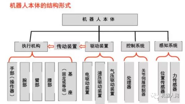
1, robot drive device
Concept: To get the robot up and running, it is necessary to set the actuator for each joint, that is, each degree of freedom of movement: to provide the motive force for each part of the robot and each joint.
Drive system: It can be hydraulic drive, pneumatic drive, electric drive, or an integrated system that combines them; it can be driven directly or indirectly driven by mechanical transmission mechanisms such as timing belts, chains, gear trains, harmonic gears, etc.
(1) Electric drive device
The electric drive has a simple energy source, a wide range of speed variations, high efficiency, and high speed and position accuracy. However, they are often associated with deceleration devices and direct drive is difficult.
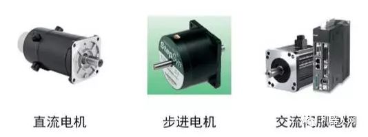
Electric drive can be divided into direct current (DC), alternating current (AC) servo motor drive and stepper motor drive. DC servo motor brush is easy to wear, and easy to form sparks. Brushless DC motors have also been used more and more widely. Stepper motor drive is mostly open-loop control, simple control but low power, mostly used in low-precision low-power robot systems.
Check the following before powering on the motor:
The Power Supply voltage is suitable (overvoltage may cause damage to the drive module); The +/- polarity of the DC input must not be connected incorrectly, the motor model or current setpoint on the drive controller is appropriate (do not start too much );
The control signal lines are securely connected, and the shielding of the industrial site (eg using twisted pair) is a good consideration;
Don't start with all the wires that need to be connected, just connect to the most basic system, and after a good run, connect them gradually.
Be sure to find out the grounding method, or use floating air.
The state of the motor must be closely observed within half an hour of the start of operation, such as whether the movement is normal, sound and temperature rise, and the problem is immediately shut down for adjustment.
(2) Hydraulic drive
It is accomplished by a high-precision cylinder and piston, and linear motion is achieved by the relative motion of the cylinder and the piston rod.
Advantages: Large power, can save the deceleration device directly connected to the driven rod, compact structure, good rigidity, fast response, servo drive with high accuracy.
Disadvantages: The need for additional hydraulic source, easy to produce liquid leakage, not suitable for high and low temperature applications, so the hydraulic drive is currently used in extra large power robot systems.
Select the appropriate hydraulic oil. Prevents the mixing of solid impurities into the hydraulic system and prevents air and water from invading the hydraulic system. Mechanical operations should be gentle and smooth mechanical operations should avoid rough, otherwise it will inevitably produce impact load, so that frequent mechanical failure, greatly reducing the service life. Pay attention to cavitation and overflow noise. Always pay attention to the sound of the hydraulic pump and relief valve during operation. If the hydraulic pump has “cavitation” noise, it cannot be eliminated after being exhausted. It should be found out after troubleshooting. Keep an appropriate oil temperature. The working temperature of the hydraulic system is generally controlled between 30 ~ 80 °C.
(3) pneumatic drive
The pneumatically driven structure is simple, clean, sensitive, and has a cushioning effect. However, compared with the hydraulic drive device, the power is small, the rigidity is poor, the noise is large, and the speed is not easy to control. Therefore, it is mostly used for a point-controlled robot with low precision.
a. It has the characteristics of high speed, simple system structure, convenient maintenance and low price. Suitable for use in medium- and low-load robots. However, due to the difficulty in achieving servo control, many robots are used in program control, such as in the upper and lower materials and stamping robots.
b. In most cases it is used in small and medium robots that implement two-position or finite-point control.
c. Most control devices currently use programmable controllers (PLC controllers). Pneumatic logic components can be used to control devices in flammable and explosive environments.
2, linear transmission mechanism
The transmission is a key part of connecting the power source and the moving link. According to the joint form, the commonly used transmission mechanism is a linear transmission and a rotary transmission mechanism.
The linear transmission method can be used for the X, Y, Z-direction driving of the Cartesian coordinate robot, the radial driving and vertical lifting driving of the cylindrical coordinate structure, and the radial telescopic driving of the spherical coordinate structure.
Linear motion can be converted into linear motion through gears, racks, nuts, and other transmission elements. It can also be driven by a linear drive motor, or it can be generated directly by the piston of a cylinder or a hydraulic cylinder.
(1) Rack and pinion device
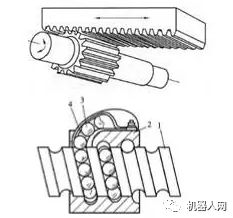
The rack is usually fixed. The rotational motion of the gear is converted into the linear motion of the pallet.
Advantages: simple structure.
Disadvantages: Large difference in return.
(2) Ball screw
The ball is embedded in the spiral groove of the screw and nut, and the ball can continuously circulate through the guide groove in the nut.
Advantages: Small friction, high transmission efficiency, no creep, high precision
Disadvantages: high manufacturing costs and complex structures.
Self-locking problem: In theory, the ball screw can also be self-locking, but the actual application does not use this self-locking, mainly because: poor reliability, or high processing costs; because the diameter and lead ratio is very large, In general, a self-locking device such as a worm gear is added.
3, rotating transmission mechanism
The purpose of using a rotary transmission mechanism is to convert the higher speed output from the drive source of the motor into a lower speed and obtain a larger torque. The most frequently used rotary transmission mechanisms in robots are gear trains, timing belts, and harmonic gears.
(1) Gear chain
a. Speed relationship
b. Torque relationship
(2) timing belt
The timing belt is a belt with many types of teeth that meshes with a timing belt pulley that also has gear teeth. When working, it is equivalent to a soft gear.
Advantages: no sliding, good flexibility, low price, high repeatability of positioning.
Disadvantages: Has a certain degree of elastic deformation.
(3) Harmonic gears
The harmonic gear consists of three main parts: a rigid gear, a harmonic generator and a flexible gear. The rigid gear is generally fixed, and the harmonic generator drives the flexible gear to rotate. main feature:
a. Larger transmission ratio, single-stage is 50-300.
b. Smooth transmission and high bearing capacity.
c. High transmission efficiency, up to 70%-90%.
d. High transmission accuracy, 3-4 times higher than that of ordinary gear transmission.
e. The return difference is less than 3'.
f. The intermediate output cannot be obtained, and the flexure wheel rigidity is low.
Harmonic transmission devices have been widely used in countries with advanced robot technology. For Japan alone, 60% of robotic drives use harmonic transmission.
The robots sent to the moon by the United States use harmonic transmissions at their joints. One of the upper arms uses 30 harmonic transmission mechanisms.
For the former Soviet Union, the mobile robot “moon landing” that was sent to the moon, the eight wheels installed in pairs were driven by a closed harmonic transmission mechanism. ROHREN, GEROT R30 robots developed by Volkswagen AG and VERTICAL 80 robots developed by Renault of France have adopted harmonic transmission mechanisms.
4, robotic sensing system
a. The sensor system consists of an internal sensor module and an external sensor module to obtain meaningful information in the internal and external environmental conditions.
b. The use of smart sensors improves the mobility, adaptability, and intelligence of the robot.
c. The use of smart sensors improves the robot'S mobility, adaptability, and intelligence.
d. For some special information, sensors are more effective than human sensory systems.
5, robot position detection
Rotary optical encoders are the most commonly used position feedback devices. Photodetectors convert light pulses into binary waveforms. The rotation angle of the shaft is obtained by calculating the number of pulses and the direction of rotation is determined by the relative phase of the two square wave signals.
The inductive synchronizer outputs two analog signals - the sine and cosine signals of the shaft angle. The rotation angle of the shaft is calculated from the relative amplitudes of these two signals. Inductive synchronizers are generally more reliable than encoders, but their resolution is lower.
Potentiometers are the most direct form of position detection. It is connected in a bridge and can generate a voltage signal proportional to the angle of rotation of the shaft. However, due to low resolution, poor linearity and sensitivity to noise.
The tachometer can output an analog signal that is proportional to the speed of the shaft. If there is no such speed sensor, the speed feedback signal can be obtained by the difference of the detected position with respect to time.
6, robot force detection
Force sensors are usually mounted on the operating arm in the following three positions:
a. Mount on the joint drive. The torque or force output of the driver/reducer itself can be measured. However, the contact force between the end effector and the environment cannot be well detected.
b. Mounted between the end effector and the end joint of the operating arm, the wrist force sensor can be called. Typically, three to six force/torque components applied to the end effector can be measured.
c. Mounted on the "fingertip" of the end effector. Usually, these forces feel that the strain gauge is built into the finger and can measure one to four force components acting on the fingertip.
7. Robot-environment interaction system
a. The robot-environment interaction system is a system that realizes the interconnection and coordination between the industrial robot and the equipment in the external environment.
b. Industrial robots and external equipment are integrated into one functional unit, such as manufacturing and manufacturing units, welding units, and assembly units. It can also be integrated with multiple robots, multiple machine tools or devices, multiple parts storage devices, and the like.
c. It may also be a functional unit that multiple robots, multiple machine tools or devices, multiple parts storage devices, etc. are integrated to perform complex tasks.
8, human-computer interaction system
The human-computer interaction system is a device that allows an operator to participate in robot control and contact the robot. The system can be divided into two categories: instruction given device and information display device.
Second, the common kinematic configuration of industrial robots
1, Cartesian operating arm
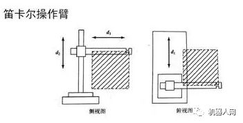
Advantages: Very easy to implement by computer control, easy to reach high precision.
Disadvantages: impede work, and occupy a large area, low speed, and poor sealing.
1 welding, handling, loading and unloading, packaging, palletizing, demolition, inspection, testing, classification, assembly, labeling, coding, coding, (soft copy) spray, target follow, explosives and a series of work.
2 It is especially suitable for flexible operation of many varieties and batches, which plays an important role in stabilizing, improving product quality, increasing labor productivity, improving working conditions and rapid product replacement.
2, hinge type operating arm (joint type)
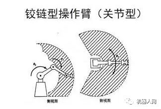
The joints of the joint robot are all rotating, similar to the human arm, the most common structure in industrial robots. Its scope of work is more complex.
1 Rapid testing and product development of automotive parts, molds, sheet metal parts, plastic products, sports equipment, glass products, ceramics, aviation, etc.
2 Coordinate measurement and error detection of manufacturing quality control such as body assembly and general machinery assembly.
3 Rapid prototyping of antiques, artworks, sculptures, cartoon character modeling, and portrait products.
4 On-site vehicle measurement and inspection.
5 Human body shape measurement, bone and other medical equipment production, body shape production, medical cosmetic surgery and so on.
3, SCARA operating arm
SCARA robots are often used for assembly operations. The most notable feature is that they have greater flexibility in movement in the xy plane and strong stiffness along the z axis, so it is selectively flexible. This kind of robot has got a better application in assembly work.
1 Largely used for assembly of printed circuit boards and electronic components
2 Moving and picking up objects, such as integrated circuit boards
3 Widely used in plastics industry, automobile industry, electronic product industry, pharmaceutical industry and food industry.
4 parts and assembly work.
4, spherical coordinate operating arm

Features: The working range near the center bracket is large, two rotary drive devices are easy to seal and cover a large working space. However, this coordinate is complicated, difficult to control, and there is a problem with the seal of the linear actuator.
5. Cylindrical coordinate operating arm
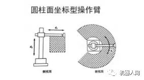
Advantages: The calculation is simple; the straight part can be driven by hydraulic pressure and can output a large amount of power; It can penetrate into the cavity type machine.
Disadvantages: The space that can be reached by its arms is restricted and it cannot reach the space near the pillar or near the ground. The linear drive part is difficult to seal and dustproof; when the rear arm is working, the rear end of the arm will touch other objects within the working range.
6, redundant agencies
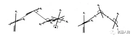
In general, 6 degrees of freedom are required for spatial positioning. Using additional joints can help the body avoid strange singularities. The following figure shows the 7-DOF operating arm configuration
7, closed-loop structure
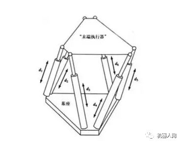
The closed-loop structure can improve the stiffness of the mechanism, but it will reduce the range of motion of the joint and reduce the working space.
1 motion simulator;
2 parallel machine tools;
3 Micro-operational robots;
4 force sensor;
5 Cell manipulation robots in biomedical engineering can achieve cell injection and segmentation;
6 Microsurgical robots;
7 attitude adjustment devices for large radio telescopes;
8 Hybrid equipment, such as SMT's Tricept hybrid manipulator module is a successful model based on the modular design of the parallel mechanism unit.
Third, commonly used materials for industrial robots
1) Carbon structural steel and alloy structural steel These materials have good strength, especially alloy structural steels, whose strength has been increased by 4 to 5 times, elastic modulus E is large, and anti-deformation ability is strong. It is the most widely used material.
2) Aluminum, aluminum alloys and other light alloy materials The common feature of these materials is their light weight and low modulus of elasticity E, but the material density is small, so the E/p ratio can still be compared with steel. The quality of some rare-earth aluminum alloys has been significantly improved, such as the addition of 3.2% (by weight) lithium aluminum alloys, the elastic modulus increased by 14%, and the E/ρ ratio increased by 16%.
3) Fiber-reinforced alloys Such alloys as boron-fiber-reinforced aluminum alloys and graphite-fiber-reinforced magnesium alloys have E/ρ ratios of 11.4×10⁷ and 8.9×10⁷, respectively. This fiber-reinforced metal material has a very high E/ρ ratio but is expensive.
4) Ceramics Ceramic materials have good quality, but they are brittle and difficult to process. Japan has already prototyped ceramic robot arm samples for use on small, high-precision robots.
5) Fiber-Reinforced Composites These materials have excellent E/ρ ratios, and they also have the outstanding advantage of large damping. Traditional metal materials cannot have such large damping, so more and more examples of composite materials are applied to high-speed robots.
6) Viscoelastic large damping material Increasing the damping of the robot link is an effective method to improve the dynamic characteristics of the robot. There are many methods currently used to increase the damping of structural materials. One method that is most suitable for robots is to apply constrained layer damping to the original component with a viscoelastic and large damping material.
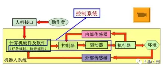
Fourth, the control system of industrial robot
1, the robot control system
The purpose of "control" is to cause the controlled object to produce the desired behavior of the controller. The basic condition of "control" is to understand the characteristics of the controlled object. "Substantially" is the control of the output torque of the driver.
2, robot teaching principle
The basic working principle of the robot is teaching reproduction; the teaching is also called guidance, that is, the user guides the robot and operates the actual task step by step, and the robot automatically memorizes the position and posture of each movement taught during the guidance process. , motion parameters/process parameters, etc., and automatically generate a program that continuously performs all operations. After completing the teaching, just give the robot a start command and the robot will exactly follow the teaching action and complete the operation step by step.
3, robot control classification
1) According to whether the feedback is divided into: open-loop control, closed-loop control; open-loop precise control of the conditions: accurately know the model of the controlled object, and this model remains unchanged during the control process.
2) According to the desired control quantity is divided into: position control, force control, hybrid control; position control is divided into: single joint position control (position feedback, position velocity feedback, position velocity acceleration feedback), multi-joint position control, multi-joint position control Is divided into motion control, centralized control; force control is divided into: direct force control, impedance control, force control;
3) Intelligent control methods: fuzzy control, adaptive control, optimal control, neural network control, fuzzy neural network control, expert control, and others;
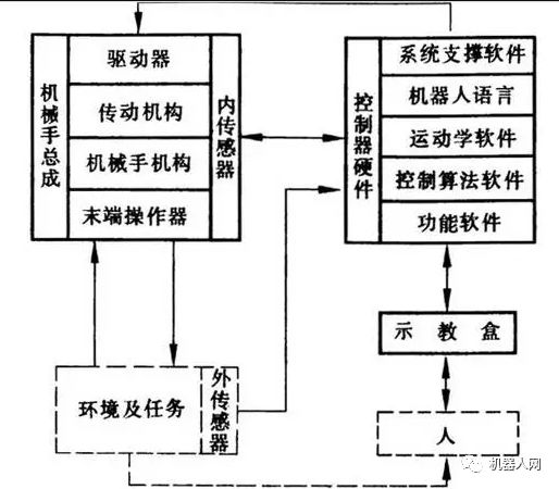
4, control system hardware configuration and structure
Because the robot control process involves a large number of coordinate transformations and interpolation operations as well as lower-level real-time control, the current robot control system most of the structure uses a hierarchical structure of the microcomputer control system, usually using two Computer servo control system.
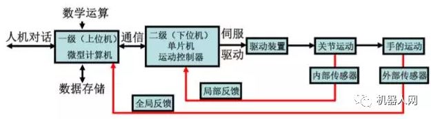
1) Specific process:
After the master computer receives the job instruction input by the worker, it first analyzes the interpretation instruction to determine the hand movement parameters.
Then perform kinematics, dynamics and interpolation operations, and finally get the coordinated motion parameters of each joint of the robot. These parameters are output via the communication line to the servo control level as a given signal for each joint servo control system. The joint driver converts this signal D/A and drives each joint to produce coordinated motion. The sensor feeds back the motion output signals of each joint back to the servo control level computer to form a partial closed loop control, thereby more accurately controlling the motion of the robot hand in space.
2) Two control methods based on PLC motion control:
a. Use some of the PLC's output ports to use the pulse output command to generate a pulse-driven motor while using a general-purpose I/O or counting unit to achieve closed-loop position control of the motor.
b. Using the PLC externally extended position control module to realize the closed-loop position control of the motor is mainly controlled by the high speed pulse method, which belongs to the position control method, and the general point-to-point position control method is more.
Our harmonizing lines force control system, Harmonizing lines constant force actuator, Harmonizing lines active contact flange have many advantages over other grinders. It can realize flexible grinding, quick repsond to surface changing, and instant adjusting. Traditional mechanic hand lacks flexibility, and it is not easy to adjust, hard to realize mass production.
Harmonizing lines constant force actuator, Harmonizing lines active contact flange, Harmonizing lines force control system
Heyuan Electronic Technology Co., Ltd. http://www.szactivecontactflange.com